Physical Address
304 North Cardinal St.
Dorchester Center, MA 02124
Physical Address
304 North Cardinal St.
Dorchester Center, MA 02124

server Characteristics
I/O Datapath
| – Data Flow: User/application requests enter via the LAN. Network Interface Cards (NICs): Enable I/O traffic into the server. Can be integrated on the system board or expandable (plugged into riser ports). Memory Module: Temporarily holds data during processing. CPU: Provides computational power and operational control. Hardware RAID Controller: Offloads disk control tasks from the CPU. Disk Drive: Stores and retrieves data when not in memory. | 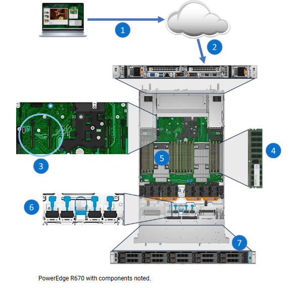 |
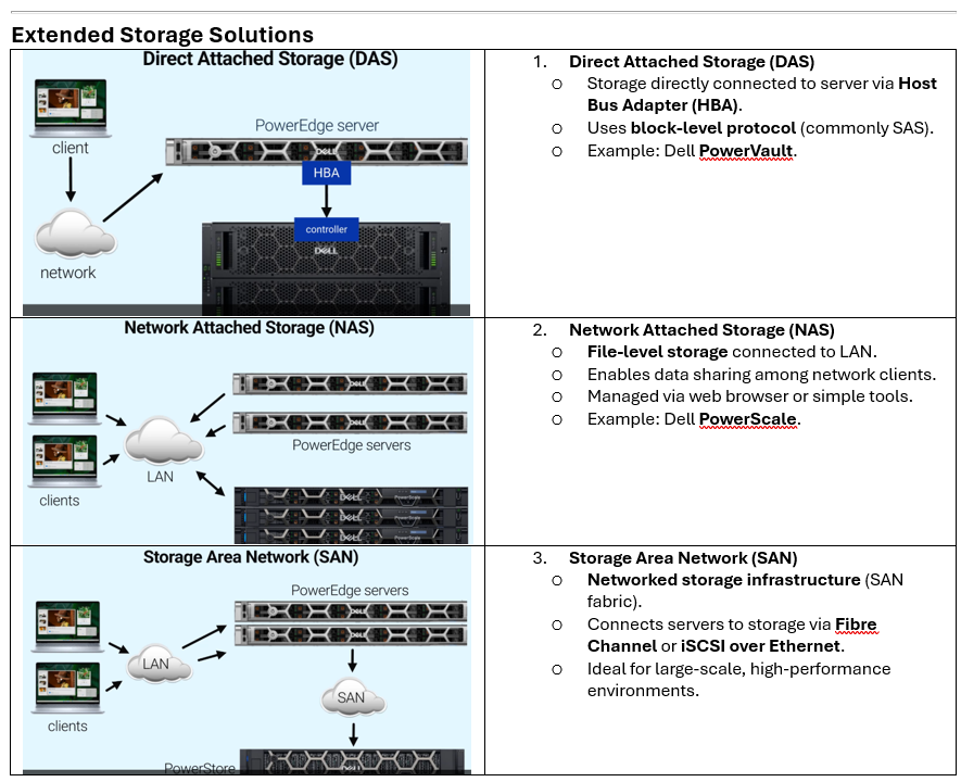
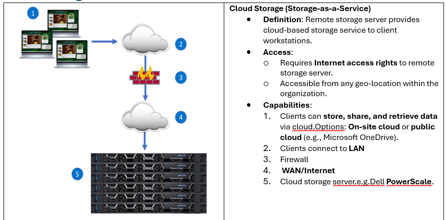
Advantages and Disadvantages of Storage Solutions
| Solution | Advantages | Disadvantages |
| Solution | Advantages | Disadvantages |
| DAS | Minimum hardware cost Simplified setup Management is for small environments. | Limited scalability Potential single points of failure at each server Difficult to manage for larger environments. |
| NAS | Efficient file storage and management Added to existing LANs and can co-exist with SANs. Simplified management | Not well suited to applications that require block-level storage. Limited scalability Relies on TCP/IP networks |
| SAN | Exceptional performance Extremely fault tolerant and highly reliable Highly scalable Centralized management Uses separate network for storage – can reduce load on LAN Shared access to storage pools, backup, restore, and Disaster Recovery (DR) services. | Higher initial cost More complex to deploy Leverage few vendor-specifics |
| CLOUD | Increased accessibility to data from any device with an Internet connection Convenient file sharing, and scalability to adjust storage needs as required. Easy access, collaboration, and flexible storage capacity that is based on organization needs | Reliance on a stable Internet connection Potential security concerns that relate to data privacy as the data may be stored on a third-party server. Potential cost increases depending on the amount of storage and the growth of the storage. |
Storage Capacity Planning
SATA (Serial ATA)
SAS (Serial Attached SCSI)
SSD (Solid State Drive)
NVMe (Non-Volatile Memory Express)
E3 (EDSFF – Enterprise & Data Center SSD Form Factor)
BOSS (Boot Optimized Storage Solution)
Backplane
Common RAID Levels
RAID Controller Overview
PowerEdge RAID Controller (PERC)
Key Components
RAID Levels
Disk Striping
Data Redundancy
Parity-Based RAID Levels
Fault Tolerance
| Server Purpose | Essential Factors | RAID Level |
| Provide video creation and editing capabilities to a group of media experts at a multimedia company. | Speed | RAID 0 |
| Host a server operating system or database. | Reliability | RAID 1 |
| Implement a transactional database requiring high performance and maximum protection. | Performance and Reliability | RAID 10 |
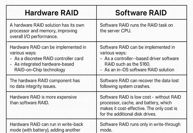
Software RAID
Hardware RAID
Virtual Memory
Common Management Tools
Server Management Overview
No single tool manages all aspects of a data center; multiple tools are used.
Management approaches:
Out-of-Band (OOB): Independent of OS, agentless.
In-Band (IB): OS-dependent.
Out-of-Band (OOB) Tools
iDRAC:
Deploy, monitor, configure, update, troubleshoot remotely.
Agentless, no OS dependency.
Lifecycle Controller:
Embedded management for OS deployment, configuration, updates.
Access via F10 during boot.
RACADM: CLI tool for configuration (get/set commands).
System Setup Utility:
BIOS settings (boot order, RAID mode, passwords).
Access via F2 during boot.
Virtual Console: Remote KVM access via iDRAC UI.
LCD Control Panel:
Displays system info, error messages, iDRAC IP.
Quick Sync:
Bluetooth/Wi-Fi access for monitoring/configuration via mobile device.
In-Band (IB) Tools
OpenManage Enterprise:
Web-based management for thousands of devices (including third-party).
Deployable on Hyper-V, ESXi, or KVM.
iSM (iDRAC Service Module):
Extends iDRAC features into OS for lifecycle logs.
Server Setup and Configuration Utilities
Launching Utilities During Boot
Purpose: Configure server settings before OS loads.
Common Utilities:
System Setup (F2)
Configure basic server settings (boot order, RAID mode, passwords).
Lifecycle Controller (F10)
Advanced embedded management: OS deployment, configuration, updates, maintenance, diagnostics.
Boot Manager (F11)
Select boot options and diagnostic utilities.
Lifecycle Controller
Preboot Management:
Graphical interface or remote console via standards-based APIs or scripting.
Key Features:
Eliminates need for physical media.
Firmware updates from local or network sources.
Hardware configuration.
OS deployment with embedded driver repositories (Windows & Linux).
Platform-specific diagnostics.
iDRAC Licensing
License determines feature access:
Express: Standard on XE-series servers.
Enterprise / Datacenter / SEKM: Available as upgrades; richer feature set.
Key Points:
Higher-tier licenses enable advanced management (recommended for XE deployments).
Licensing options differ by generation (e.g., iDRAC9 vs iDRAC10).
Tip: Always check official documentation for the latest feature-to-license mapping.
iDRAC Password Features
Factory-Generated Password (PowerEdge 16G):
Printed on Service Tag (Luggage Tag).
12-character alphanumeric, uppercase letters only.
Certain characters omitted to avoid ambiguity.
Legacy Option:
Username: root
Password: calvin (available at Point-of-Sale).
iDRAC Direct
Purpose: Direct laptop-to-server connection for initial setup.
Pre-17G:
Micro-USB port.
Access via https://idrac.local or https://169.254.0.3.
LED blinks green for activity.
17G:
USB Type-C port (dual-purpose: Host/iDRAC).
Default mode = Host; switch to iDRAC by pressing System ID button for 5–10 sec.
LED indicators:
Off = Host mode.
Solid green = iDRAC mode.
Blinking green = Activity.
Solid amber = Communication failure.
Blinking amber = System fault.
iDRAC Menu Overview
Dashboard:
Landing page with system health, OS info, jobs, firmware versions.
Launch Virtual Console for remote OS access.
System:
High-level overview of inventory, metrics, and component status.
Storage:
Details on controllers, drives, virtual disks, and enclosures.
Configuration:
Options for power management, virtual console, licenses, BIOS, and system settings.
Maintenance:
Logs, firmware upgrades, troubleshooting tools.
iDRAC Settings:
Connectivity, services, user management, and iDRAC-specific settings.
Supported Operating Systems and Compatibility
Key Points from Your Text
Operating System Role: Manages hardware resources and communication between system software and hardware.
Supported OS Examples:
VMware ESXi 8.0 – Virtualization
Windows Server 2019/2022 – Database hosting, Active Directory
Red Hat Enterprise Linux (RHEL 8.6/9.0) – Enterprise apps, cloud/virtualization
Ubuntu 22.04.x – Web hosting, development environments
SUSE SLES 15 SP4 – HPC, SAP applications
Tip: Use bare metal for Active Directory.
Compatibility: Check ISM and HCL for supported OS versions.
What is an HCL?
A Hardware Compatibility List (HCL) is an official list of hardware components and peripheral devices that have been tested and certified to work with a specific operating system or platform.
PERC Types Overview
1. Mini PERC
Description: Installed in a dedicated slot on the motherboard.
Examples:
PERC 10 series: H710, H310, H730, H330, H740.
2. Front PERC (fPERC)
Description: Installed in the front slot of the server chassis.
Examples:
PERC 10.6 & PERC 11: H745, H755.
PERC 12: H965i.
RAID Overview
RAID (Redundant Array of Independent Disks) combines multiple physical drives into logical units for:
Performance (faster reads/writes)
Redundancy (data protection)
Or both.
Common RAID Levels
RAID Level
Concept
Min Drives
Pros
Cons
RAID 0
Striping
2
High performance
No redundancy; single disk failure = data loss
RAID 1
Mirroring
2
High reliability; fast recovery
Cuts usable capacity in half
RAID 3
Striping + parity (single parity disk)
3
Data protection
Bottleneck on parity disk
RAID 5
Striping + distributed parity
3
Good balance of performance & redundancy
Slower writes; rebuild time
RAID 6
Striping + dual parity
4
Survives 2 disk failures
Slower writes; more overhead
RAID 10
Mirroring + striping
4
High performance & redundancy
High cost; needs even number of dis
RAID Controller Overview
Definition: A RAID controller is an integrated device or expansion card that provides RAID services for virtualized disk drives.
Function:
Presents multiple storage devices as a single logical drive to the OS.
Organizes and communicates data between the server and storage media.
Supports SAS, SATA, SSD, and NVMe SSD drives.
✅ PowerEdge RAID Controller (PERC)
Role: Manages and monitors PowerEdge server drives.
Integration: Connects directly to the backplane and system board.
Types:
Mini PERC: Installed on motherboard slot (e.g., H710, H730, H740).
Front PERC (fPERC): Installed in front chassis slot (e.g., H965i).
Has its own processor and memory, reducing CPU dependency.
✅ fPERC Features (H965i Example)
Components:
PCIe connection
Backplane connections
Battery and battery connector
Heat sink
Power connection
System board connection
Exactly! RAID levels beyond RAID 0 introduce redundancy mechanisms like mirroring or parity, which protect against:
Unrecoverable sector read errors (bit-level corruption)
Complete physical drive failures
This is why RAID 1, 5, 6, and 10 are widely used in enterprise environments—they balance performance, capacity, and fault tolerance.
✅ Quick Insight:
RAID 0 → Performance only (no protection)
RAID 1, 5, 6, 10 → Protection against disk failures and read errors
Higher RAID levels = more drives + more parity calculations = better reliability but slower writes
RAID Levels Summary Table
RAID Level
Min Drives
Redundancy
Performance
Usable Space Formula
Best Use Case
RAID 0
2
None
Highest
n + n (sum of all drives)
Video editing, gaming
RAID 1
2
100%
High read, normal write
n – 1 (half of total)
Financial apps, small DB
RAID 5
3
Single parity
High read, slower write
n – 1
General-purpose servers
RAID 6
4
Dual parity
High read, slower write
n – 2
Large drives, critical data
RAID 10
4 (even pairs)
Mirroring + striping
Highest + redundancy
50% of total
High-performance DB
RAID 10
Minimum Drives: 4 (pairs for mirroring)
Usable Space Formula:![]() Example: 4 × 400 GB → 800 GB usable.
Example: 4 × 400 GB → 800 GB usable.
Fault Tolerance: Multiple failures allowed if not in same mirrored pair.
Pros: High performance, fast recovery, great for critical data.
Cons: High cost (50% overhead).
Use Case: High-load databases, critical applications.
✅ RAID 50
Structure: RAID 0 across multiple RAID 5 sets.
Minimum Drives: 6 (two RAID 5 sets of 3 drives each).
Usable Space Formula:![]() Example: (3 × 400 GB – 1 drive) × 2 sets = 1600 GB.
Example: (3 × 400 GB – 1 drive) × 2 sets = 1600 GB.
Fault Tolerance: 1 drive per RAID 5 set.
Pros: Better performance than RAID 5, good redundancy.
Cons: Expensive, complex.
Use Case: Balanced performance and reliability for large storage pools.
✅ RAID 60
Structure: RAID 0 across multiple RAID 6 sets.
Minimum Drives: 8 (two RAID 6 sets of 4 drives each).
Usable Space Formula:![]() Example: (4 × 400 GB – 2 drives) × 2 sets = 1600 GB.
Example: (4 × 400 GB – 2 drives) × 2 sets = 1600 GB.
Fault Tolerance: 2 drives per RAID 6 set.
Pros: Highest redundancy, good read performance.
Cons: Very expensive, slower writes.
Use Case: Mission-critical systems needing maximum fault tolerance.
🔍 Key Differences:
RAID 10 → Best for speed + redundancy (databases).
RAID 50 → Good balance for large arrays.
RAID 60 → Maximum fault tolerance for enterprise workloads.
Dell OpenManage Secure Enterprise Key Manager (SEKM)
A centralized key management solution embedded in PowerEdge servers for data-at-rest encryption and compliance.
Key Features
Highly-Available KMS Cluster
Multiple servers form a cluster to avoid single points of failure.
Ensures keys are always accessible.
Key Retrieval via iDRAC
During power events, drives lock.
iDRAC securely retrieves keys from the KMS to unlock drives.
Built-In PowerEdge Security
Silicon root of trust
Secure boot cycle
Signed firmware
BIOS recovery and other security controls.
Keys Assigned by External KMS
Self-encrypting drives (SEDs) receive keys from external KMS.
Keys unlock drives for data flow.
Linear Scalability
Encryption handled by each drive’s hardware.
Scales easily while meeting regulatory requirements.
Module Overview: PowerEdge Server Networking
After completing this module, you will be able to:
Describe the OSI Model and its seven layers.
Discuss Physical & Network Layers:
Ethernet cables (types, speeds, standards)
Internet Protocol
Explain the Application Layer:
Network services and common applications
Define Virtualization and its benefits in server infrastructure.
Explore Common Networking Solutions.
Network Nodes
Servers: Core of the network; provide services like email, file sharing, web hosting.
Switches: Connect devices within a local network.
Routers: Connect multiple networks.
Access Points: Enable wireless connectivity.
Firewalls: Protect against unauthorized access and attacks.
End Nodes: Workstations, notebooks, tablets, printers, backup devices.
OSI Model Layers
Physical – Hardware, cables, signals.
Data Link – MAC addressing, Ethernet.
Network – IP addressing, routing.
Transport – TCP/UDP, reliability.
Session – Communication sessions.
Presentation – Data formatting, encryption.
Application – Services like HTTP, FTP, DNS.
Virtualization
Definition: Abstracts physical resources into virtual resources.
Benefits:
Efficient resource utilization
Scalability
Isolation for security
Easier management
OSI Model Layers (7 Layers)
Layer
Function
Examples
7. Application
Interface for end-user interaction with the network. Creates/receives data.
Email clients, web browsers
6. Presentation
Translates, formats, encrypts/decrypts data for the application layer.
SSL/TLS, JPEG, ASCII
5. Session
Manages sessions between systems (setup, maintain, terminate). Provides authentication.
APIs, NetBIOS, RPC
4. Transport
Ensures reliable delivery, sequencing, and error checking of data packets.
TCP, UDP
3. Network
Routes data using logical addressing (IP). Handles packet forwarding.
IP, Routers
2. Data Link
Node-to-node transfer, error correction. Includes MAC & LLC sublayers.
Ethernet, Switches, MAC addresses
1. Physical
Transmits raw bits over physical medium (cables, voltages, RF).
NICs, cables, hubs, modems


✅ Ethernet Basics
OSI Layers: Operates at Layer 1 (Physical) and Layer 2 (Data Link).
Functions:
Sends frames between devices using MAC addresses.
Broadcasts frames to all devices in the local network.
Performs error checks on frames.
✅ Ethernet Standards (IEEE 802.3)
Example: 10GBASE-T
10G → Speed (10 Gigabits per second)
BASE → Baseband signaling
T → Media type (Twisted Pair)
F → Fiber optic (alternative media)
✅ Broadcast Domains
Definition: A set of devices that receive broadcast frames from any device in the domain.
How It Works:
Devices connected to the same switch or hub share a broadcast domain.
Broadcasts occur at Layer 2 (Data Link) when the sender doesn’t know the recipient’s MAC address.
Physical Layer: Cabling and Connectors
Purpose: Enables wired data transfer between devices in Ethernet networks.
Twisted-Pair
Common Media: Twisted-Pair Ethernet cables with RJ45 connectors.
Categories:
Cat 5 → 10/100 Mbps, 100 MHz
Cat 5e / Cat 6 → 1 Gbps, 100–250 MHz
Cat 6a / Cat 7 → 10 Gbps, 500–600 MHz
Cat 8 → 25–40 Gbps, 2000 MHz (up to 30m)
Ethernet Cable Types
All Ethernet cables use twisted pairs to reduce interference. Shielding adds extra protection against EMI (Electromagnetic Interference).
1. UTP (Unshielded Twisted Pair)
Common Use: Between system and wall outlet; desktop communication.
Pros: Cost-effective, easy to install.
Cons: Less protection against EMI.
2. STP (Shielded Twisted Pair)
Common Use: High-speed networks (e.g., 10 GbE).
Why: Sensitive to EMI from nearby motors, generators, HVAC systems.
Construction: Metallic shield + foil wrap around wire pairs.
UTP vs STP Comparison
Feature
UTP (Unshielded Twisted Pair)
STP (Shielded Twisted Pair)
Use Case
Fast transmissions where EMI is not a factor
High-speed networks (up to 40 Gbps) in EMI-heavy areas
Basic Structure
Twisted wires without shielding
Twisted wires enclosed in foil or braided mesh shield
Definition
Two insulated copper conductors twisted together
Same as UTP + metal foil to block electromagnetic noise
Installation
Easy to install, lightweight
Harder to install, heavier and bulkier
Cost
Inexpensive
More expensive
Transmission Rate
Lower compared to STP
Higher data rates
Noise Susceptibility
High
Low (effective up to 10–25 meters)
Modular Transceivers for Enterprise Networking
Types & Speeds:
SFP+ → 10 Gbps
SFP28 → 25 Gbps
QSFP → 40 Gbps
QSFP28 → 100 Gbps
Use Case: High-speed, high-density networking environments (data centers, enterprise backbones).
Patch Cable Overview
Purpose: Connects network switches to servers and storage in LANs.
Role: Integral part of structured cabling systems.
Types
Copper Patch Cable
Typically made with stranded copper for flexibility.
Solid copper used for permanent runs (walls, ceilings, conduits).
Common connector: RJ45.
Fiber Patch Cable
Ends capped with fiber connectors (e.g., LC, SC).
Connects to optical switches, transmitters, receivers, and terminal boxes.
Used for high-speed, long-distance connections.
Onboard Network Cards
Evolution: Servers moved away from fixed integrated NICs to modular options for flexibility.
Types:
LAN on Motherboard (LOM): Built-in network interface on the server motherboard.
OCP (Open Compute Project) NICs: Modular cards that allow customization.
Benefits:
Flexible choice of port speed (1GbE, 10GbE, 25GbE, etc.).
Choice of media type (Copper, Fiber, SFP modules).
Easier upgrades without replacing the entire motherboard.
Open Compute Project (OCP) NIC Overview
Supported Standard: OCP 3.0
Integration: NIC ports are on the OCP card, which connects to the system board.
Example: PowerEdge R760 supports:
Up to two 10/100/1000 Mbps NIC ports via LOM and OCP card.
✅ OCP 3.0 Card Features (16G & 17G PowerEdge Servers)
Feature
Support
Form Factor
Small Form Factor (SFF)
PCIe Gen
Gen4
Max PCIe Width
x8 or x16
Max No. of Ports
4
Port Types
BaseT, SFP, SFP+, SFP28, SFP56
Supported Speeds
4×1 GbE, 4×10 GbE, 2×10 GbE, 2×25 GbE, 4×25 GbE
NC-SI
Yes
SNAPI
Yes
Wake-on-LAN (WOL)
Yes
Power Consumption
15 W ~ 150 W
Network Layer: Internet Protocol
Pv4 Addressing
IPv4 uses 32 bits divided into 4 octets (8 bits each).
IPv6 Addressing
IPv6 uses 128 bits, written in hexadecimal, separated by colons.
Example: fe80::52d8:dd60:730d:518b
IP Address Classes Overview
Class
First Octet Range
High-Order Bits
Format
Default Mask
Networks
Hosts per Network
A
1–126
0
N.H.H.H
/8 (255.0.0.0)
126
16,777,214
B
128–191
10
N.N.H.H
/16 (255.255.0.0)
16,382
65,534
C
192–223
110
N.N.N.H
/24 (255.255.255.0)
2,097,150
254
D
224–239
1110
Multicast
N/A
N/A
N/A
E
240–254
1111
Experimental
N/A
N/A
N/A
Tip:
127.x.x.x is reserved for loopback (testing local machine).
Class D → Multicast (e.g., video conferencing).
Class E → Research/experimental.
Private IP Ranges
Class
Private Range
Subnet Mask
A
10.0.0.0 – 10.255.255.255
255.0.0.0 (/8)
B
172.16.0.0 – 172.31.255.255
255.240.0.0 (/12)
C
192.168.0.0 – 192.168.255.255
255.255.0.0 (/16)
Note:
Private IPs cannot route on the public Internet without NAT.
APIPA (169.254.x.x) auto-assigns IP if DHCP fails.
Static vs Dynamic IP
Dynamic IP: Assigned by DHCP, changes over time, uses IP pools.
Static IP: Manually configured, fixed address.
Session and Application Layer
What is a Protocol?
A protocol is a set of rules or a “language” that devices use to communicate.
Examples:
CIFS (Common Internet File System) → Used by Windows servers for file sharing.
NFS (Network File System) → Used by Linux servers for file sharing.
Session Layer
Acts as a gatekeeper:
Verifies who can access data.
Controls scope of access (broad or narrow).
Application Layer
Provides services to process client requests.
Application = Service (e.g., database, ERP).
Server = Infrastructure where the service runs.
Example Flow:
Client requests data.
Server queries storage.
Storage sends data to server.
Server sends data to client.
Examples of Services
Transactional environments
Databases
Client/server environments
High-performance computing
Simulators
Metrics analysis
HR, accounting, ERP applications
Server Role
A role = Features + services needed for a specific function.
Roles determine:
Hardware requirements
Applications to run
Server size (based on number of roles and workload)
Application Layer: Common Applications
Network Services at the Application Layer
Network services enable:
Node communication
Authentication & Authorization
Data access
Typically, these services run on servers.
Key Network Services
1. DHCP (Dynamic Host Configuration Protocol)
Purpose: Dynamically assigns IP addresses, subnet masks, gateways, and other parameters.
Model: Client/Server
Process:
Discover → Client broadcasts request.
Offer → DHCP server offers IP.
Request → Client requests offered IP.
ACK → Server acknowledges and assigns IP.
Renew → Client periodically renews lease.
ACL
2. ARP (Address Resolution Protocol)
Purpose: Maps IP addresses to MAC addresses.
Mechanism: Maintains an ARP cache table with static and dynamic mappings.
3. DNS (Domain Name System)
Purpose: Maps domain names to IP addresses.
Example: https://www.dell.com/en-us → 143.166.147.101
Process:
Client queries DNS server for IP.
DNS server responds with IP.
Client uses IP to connect to resource.
4. NTP (Network Time Protocol)
Purpose: Synchronizes system clocks to a single source.
Reference: UTC (Coordinated Universal Time)
Model: Client/Server
NTP server syncs with atomic clock.
Clients sync with NTP server.
Virtualization Overview
What is Virtualization?
Definition: Virtualization uses a hypervisor to allow one physical server to act as multiple logical machines (Virtual Machines or VMs).
Purpose: Run multiple applications on a single physical server without needing separate hardware for each.
Benefits of Virtualization
Cost Savings: Fewer physical servers → lower hardware costs.
Space Efficiency: Reduced floor space in data centers.
Energy Savings: Lower power, cooling, and heating requirements.
Green Technology: Helps avoid building new data centers.
Flexibility: Run different OS versions and applications on the same hardware.
Testing & Development: Create isolated environments for testing without impacting production.
Virtual Infrastructure
Physical Layer: Servers, storage, networking.
Virtualization Layer: Hypervisor manages resource allocation.
Virtual Machines: Each VM has its own OS and applications, isolated from others.
Use Cases
Production environments: Maximize resource utilization.
Testing multiple OS versions: Hyper-V or similar tools simplify VM creation.
Virtual networking: Create multi-machine environments for development and demos without affecting production networks.
What is a Hypervisor?
A hypervisor (Virtual Machine Monitor) is a hardware virtualization technology that allows multiple guest operating systems (OS) to run on a single physical host.
Each guest OS appears to have its own CPU, memory, and network resources, but these are shared from the host.
Types of Hypervisors
Type 1 (Bare Metal)
Runs directly on hardware.
No host OS overhead.
Examples: VMware ESXi, Microsoft Hyper-V, Linux KVM.
Best for enterprise environments and large-scale virtualization.
Type 2 (Hosted)
Runs on top of a host OS.
Uses host OS for device support and memory management.
Examples: VMware Workstation, Oracle VirtualBox.
Best for development/testing and smaller environments.
Virtual Machine (VM) Advantages
Each VM behaves like a separate system with its own OS.
Enables:
Running multiple OS on one host.
Isolation for security (breaches contained within VM).
Cost savings by reducing physical hardware.
Examples:
Hyper-V supports Windows, Linux, BSD.
ESXi supports a wide range of Linux and BSD distributions.
Hypervisor Requirements (Example: Hyper-V)
OS: Windows Server 2022+
CPU: 64-bit with SLAT (Second-Level Address Translation)
Memory: Minimum 4 GB
Boot Mode: BIOS or UEFI with virtualization enabled
License: Standard or Datacenter
Hyper-V vs VMware ESXi Use Cases
Criteria
Hyper-V
VMware ESXi
Integration
Best for Microsoft environments
Supports wide OS range
Cost
Included with Windows Server
Separate licensing, higher cost
Development
Ideal for Windows app testing
Great for diverse environments
Business Size
Small to medium businesses
Large-scale enterprise
Advanced Features
Basic virtualization
Advanced (vMotion, HA, FT)
Hardware
Microsoft-certified hardware
Broad compatibility
Virtual Networking Overview
Virtual networking connects VMs, virtual servers, and other components inside a virtualized environment.
It works similarly to traditional networking but uses virtual switches instead of physical switches.
Virtual switches manage traffic between VMs and optionally between VMs and external networks.
Types of Virtual Switches
1. Private Switch
Purpose: Communication only among VMs on the same host.
Key Points:
No traffic to/from the host.
No uplink to physical NIC (pNIC).
Completely isolated from external networks.
2. Internal Switch
Purpose: Communication among VMs and the host.
Key Points:
Host OS gets a virtual adapter (vEthernet) to talk to VMs.
No uplink to pNIC → cannot reach external networks.
Useful for testing or management traffic.
3. External Switch
Purpose: Communication among VMs and external networks.
Key Points:
Must be connected to a physical NIC.
Host shares the pNIC with VMs for external communication.
Host also uses vEthernet adapter for its own traffic.
File Sharing Topology
Dell PowerEdge File Sharing Solutions
Use Case: Secure file sharing for small to medium businesses.
Server Options:
Entry-Level: PowerEdge T160, T150 → Ideal for basic file and print services.
Robust Options: PowerEdge R470, R260, T360, T350 → For higher performance and capacity.
Example: R470 rack server for small-scale file sharing.
Network Topology
Primary Server: Hosts file-sharing services.
Secondary Server: Optional for backup and redundancy.
Switch: Backbone of LAN connectivity.
Firewall: Protects against unauthorized access.
Client Devices: Access files via LAN or WAN.
Operating Systems
Windows Server: Common choice for SMB protocol and Active Directory integration.
Ubuntu/Linux: Supports NFS and Samba for cross-platform sharing.
Protocols & Services
SMB/CIFS: Windows environments.
NFS: Linux/UNIX environments.
Samba: Cross-platform file sharing.
Security Measures
Authentication: Active Directory for centralized management.
Access Control: Permissions for file access and modification.
Encryption: Protect data at rest and in transit.
High-Performance Computing (HPC) Solution
HPC and AI cluster architecture using Dell PowerEdge servers:
Cluster Components
Compute Nodes
PowerEdge servers with GPUs for compute-intensive tasks.
Examples:
XE9680 → Extreme HPC, socket-type GPUs.
XE7740 / XE7745 → HPC with PCIe GPUs.
R770 → High-performance for smaller compute tasks.
R660 / R670 → Commonly used as head nodes.
Head Node
Manages the cluster and schedules jobs.
Runs cluster management software (e.g., Microsoft HPC Pack, Slurm).
Storage Nodes
PowerVault for scalable, high-performance storage.
Use RAID 6 for redundancy.
Implement Parallel File Systems like Lustre or GPFS for fast data access.
Networking
InfiniBand for low-latency internode communication (GPU matrix).
Ethernet for management and client access.
High-speed network switches for interconnect.
LAN/WAN
Switches for client access.
Firewall for security.
Software & Services
Cluster Management: Slurm, Microsoft HPC Pack.
Parallel File System: Lustre, GPFS.
Security:
Authentication: LDAP or Active Directory.
Access Control: Permissions for compute/storage.
Encryption: Data at rest and in transit.
Generative AI Solution
GenAI and HPC cluster architecture using Dell PowerEdge servers:
Cluster Components
Compute Nodes
PowerEdge XE9680 → Flagship AI/HPC server with 8 GPUs (NVIDIA, Intel, AMD).
PowerEdge XE7740 / XE7745 → PCIe-based GPUs, up to 16 GPUs.
PowerEdge R760xa → Dual-socket server optimized for PCIe GPUs for AI training, inference, and analytics.
Head Node
Manages cluster operations and job scheduling.
Runs cluster management software.
Storage Nodes
PowerScale → Scalable, high-performance storage for AI workloads.
Networking
InfiniBand → High-speed, low-latency GPU interconnect.
Ethernet → Internal network for management and data center connectivity.
High-speed network switches for internode communication.
Software & Services
NVIDIA AI Enterprise → Accelerates AI development and deployment.
Cluster Management → Slurm or similar tools for scheduling.
Security:
Authentication: LDAP or Active Directory.
Access Control: Permissions for compute/storage.
Encryption: Data at rest and in transit.
Course Recap
Server Network Introduction
Overview of networking concepts.
OSI layers and their roles in communication.
Physical and Network Layer
Ethernet basics: cabling, connectors, standards.
Evolution of network cards.
IP addressing and its role in communication.
Application Layer
Server applications and roles:
Email services.
File transfer services.
Importance of application layer in server setups.
Application Layer: Virtualization
Virtualization concepts.
Hypervisors (Type 1 & Type 2).
Advantages of Virtual Machines.
Dell PowerEdge hypervisor requirements.
Servers in a Solution
Secure file sharing solutions.
High-Performance Computing (HPC) for complex calculations.
Robust infrastructure for Generative AI (GenAI) workloads.
What is Easy Restore?
Purpose: Automates system board replacement by restoring saved configurations.
Storage:
Uses Easy Restore Storage on the server front panel (up to 4 MB).
Data backed up automatically to a backup flash device.
What Easy Restore Backs Up
System Service Tag
Licenses
UEFI configuration
System configuration (BIOS, iDRAC, Network)
OEM ID (personality module)
Process Overview
Power on the server.
BIOS detects new system board and service tag.
Prompt appears to restore:
Service Tag
License
Diagnostics info
Option to restore system configuration via Lifecycle Controller or Hardware Server Profile.
Press Y to restore or N for defaults.
Server reboots after successful restore.
Important Notes
Does NOT back up: OS, hard drive data, firmware drivers (due to size limits).
Enabled by default on PowerEdge 14G and later.
17G servers: Use DC-SCM for Easy Restore (not system board).
Why AI Needs More Than CPUs
Traditional workflows rely on CPUs for general-purpose computing.
AI, GenAI, and ML workloads require massive parallel processing and high throughput, which CPUs alone cannot provide.
GPUs and DPUs fill these gaps by removing CPU bottlenecks.
CPU (Central Processing Unit)
Role: The “brain” of the server; executes instructions and coordinates hardware.
Performance Factors:
Clock Speed (GHz): Cycles per second.
Core Count: Determines parallel compute capability.
TDP (Thermal Design Power): Heat dissipation capacity (measured in watts).
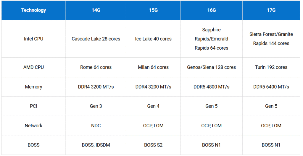
Intel Xeon Evolution in PowerEdge Servers:
14G: Cascade Lake (2nd Gen Xeon Scalable) → up to 28 cores.
15G: Ice Lake-SP (3rd Gen) → up to 40 cores.
16G: Sapphire Rapids (4th Gen) → up to 60 cores (multi-socket).
17G: Granite Rapids (Xeon 6) → up to 144 cores.
AMD EPYC Evolution:
Rome (Zen 2): 64 cores.
Milan (Zen 3): 64 cores.
Genoa (Zen 4): 128 cores.
GPU (Graphics Processing Unit)
Role: Handles massive parallel computations for AI/ML workloads.
Strength: Thousands of cores optimized for matrix operations and deep learning.
Use Cases: AI training, inferencing, HPC, GenAI.
DPU (Data Processing Unit)
Role: Offloads networking, storage, and security tasks from CPU.
Strength: Accelerates data movement and processing for distributed AI workloads.
Use Cases: High-speed networking, security, and data-intensive operations.
AMD EPYC CPU Evolution in PowerEdge Servers
Feature
14G & 15G
15G
16G
EPYC Generation
Zen 2
Zen 3
Zen 4
Industry Name
Rome
Milan
Genoa
Cores
64
64
128
PCIe / DDR
128 / 8
128 / 8
128 / 12
Clock Speed
3.4 GHz / 3200 MT/s
3.675 GHz / 3200 MT/s
3.7 GHz / 4800 MT/s
✅ GPU Architecture vs CPU
CPU: Optimized for single-thread performance, complex instruction handling, caching, and pipelining.
GPU: Optimized for parallel processing and floating-point operations, ideal for:
AI/ML/DL training and inference
Graphics rendering
Video processing
GPU Types
Socket-Based GPUs
Used in large-scale AI/GenAI workloads.
Example: PowerEdge XE9680 with 8 NVIDIA H100 GPUs.
Requires integrated PCIe switch boards, more power, and space.
PCIe-Based GPUs
Targeted for general-purpose AI/ML workloads.
Example: PowerEdge R760xa supports multiple PCIe GPUs.
Uses GPU risers with cable connections to system board and power.
✅ DPU (Data Processing Unit)
Specialized processor for data-centric tasks:
Offloads networking, storage, and security from CPU.
Improves performance and reduces latency in high-throughput environments.
Example: NVIDIA BlueField-3 DPU:
Accelerates SDN, storage, security.
Enables zero-trust data center infrastructure.
Reduces TCO and streamlines operations.
Server Memory
Role of Server Memory
Acts as high-speed, short-term storage for the CPU.
Bridges the gap between slow storage (HDD/SSD) and fast CPU.
Servers require larger capacity and bandwidth than client systems to handle multi-CPU workloads.
Memory Technology
RAM (Random Access Memory): Stores data for quick CPU access.
DDR (Double Data Rate) DRAM: Common in servers for high speed and low power.
DDR4: 1.2V
DDR5: 1.1V
DIMMs (Direct-Access Inline Memory Modules):
Must be identical in capacity and type for best performance.
No backward compatibility (e.g., DDR5 cannot be used in 14G/15G servers).
16G DDR5 DIMM Attributes
Capacity
Rank
Package Type
16 GB
1Rx8
SDP
32 GB
2Rx8
SDP
64 GB
2Rx8
SDP
128 GB
4Rx4
2H-3DS
256 GB
8Rx4
4H-3DS
Single-Die Package (SDP), where each memory chip on the DIMM contains only one die (a single piece of silicon).
3DS is three-dimensional stacking in a single package. 2H and 4H are the height of the die stack.
Memory Population Rules
Populate white slots first (1 DIMM per channel → 1 DPC) for max speed.
Example:
1 DPC: 4800 MT/s (PowerEdge R660)
2 DPC: 4400 MT/s
Populate channels equally across CPUs.
Follow assembly order (A1 → B1 → A2 → B2, etc.).
Intel Xeon Memory Architecture
P-Cores: High performance, single-channel per controller.
E-Cores: Energy efficient, two channels per controller.
ECC (Error Correcting Code):
Detects and corrects single-bit errors using Hamming code.
Adds 8 bits per 64-bit data word for error correction.
Key Considerations
Cannot mix x4 and x8 DRAM modules.
Max two RDIMMs per channel.
Populate all channels equally for balanced performance.
What is PERC?
PowerEdge RAID Controller: A family of RAID storage controllers for Dell servers.
Supported Drives:
SAS (Serial Attached SCSI)
SATA (Serial ATA)
SSD (Solid State Drives)
NVMe (Non-Volatile Memory Express)
PERC Form Factors
Rear-mounted fPERC: Mounted directly to the backplane.
Top-mounted fPERC: Secured to the chassis near the drive cage.
Adapter PERC: Installed in a PCIe riser slot.
Features:
Battery for configuration retention.
Thumb screws and short cables for connectivity.
Key Features
Hot Spare: Automatic failover when a drive fails.
Hot Swap: Replace/add drives without powering down.
Drive Roaming: Detects drives moved to different slots.
Array Expansion: Add drives to existing RAID arrays.
RAID-Level Migration: Change RAID level of virtual disks.
HBA vs PERC
HBA (Host Bus Adapter):
Passthrough device for storage/network connectivity.
No RAID functionality.
PERC:
Adds RAID, redundancy, and performance improvements.
More expensive, fewer devices supported.
PERC Generations
PERC 12
PCIe Gen4 support.
RAID levels: 0, 1, 5, 6, 10, 50, 60.
SAS/SATA/NVMe support.
NVMe speeds: 8 GT/s (Gen3), 16 GT/s (Gen4).
Throughput:
SAS 2.0 → 6 Gbps
SAS 3.0 → 12 Gbps
SAS 4.0 → 22.5 Gbps
SATA 3.0 → 6 Gbps
PERC 13
PCIe Gen5 support.
NVMe-only support.
Supercapacitor backup (vs battery in PERC 12).
Increased PHY device support (32 vs 16).
Reduced max virtual disks (simplified architecture).
PERC 12 vs PERC 13 Comparison
Category
PERC 12
PERC 13
Drive Types
SAS/SATA/NVMe
NVMe only
PCIe Speed
Gen4
Gen5
Backup
Battery
Supercapacitor
PHY Devices
16
32
Max Complex VDs
64
16
Max Simple VDs
240
64
Hot Spares
64
8
What is a Backplane?
A high-speed circuit board that connects multiple drives to a controller.
Functions:
Powers the drives.
Provides SATA, SAS, NVMe, and E3.S data I/O connections.
Acts as the data flow path between storage devices and the system board.
Key Characteristics
Failure can disconnect one or all drives.
Cable connectivity issues can disrupt data I/O.
Multiple backplane options exist across server generations.
Backplane Variations
Different servers support different backplanes for storage configurations.
Example: PowerEdge R760 can have up to 8 backplane options.
Cable complexity varies:
Some backplanes have minimal cabling (easy servicing).
Others have multiple cables (complex routing).
Connectivity
Power: Backplane power typically connects to the system board.
Signal: Backplane connects to:
fPERC card (RAID controller)
System board
PCIe Switch Board (PSB) in XE-series servers.
Front I/O (FIO): Different connectivity options for 17G servers.
Examples
8 x 2.5-inch NVMe backplane (compact).
24 x 2.5-inch NVMe passive backplane (large-scale storage).
E3.S backplane module in R770 with four signal cables to system board.
Network Interfaces for Connectivity
Purpose: Connect servers to LAN, SAN, or WAN for:
Cluster creation
Management and troubleshooting
Interfaces can be onboard or modular cards.
Types of Network Interfaces
1. LAN On Motherboard (LOM)
Provides 2x 1GbE ports for basic connectivity.
Replaceable without replacing the entire system board.
2. OCP (Open Compute Project) Cards
Connect to PCIe bus via dedicated connector.
Benefits:
Removable networking card.
Flexible speed options (10Gb, 25Gb, 50Gb, etc.).
Does not consume a standard PCIe slot.
Form Factor: Small Form Factor (SFF).
Replaces: Older Network Daughter Cards (NDC).
3. Rear I/O (RIO) Card
Provides additional connectivity and management ports:
iDRAC port (chipset on system board)
VGA
USB
ID button
Chassis intrusion switch
Optional serial connector
Enhances scalability and flexibility.
4. DC-SCM (Data Center Secure Control Module)
Combines rear I/O, iDRAC, and TPM in one card.
External access:
iDRAC port
VGA
USB ports
Integrated:
iDRAC
TPM
Attic card connector (for optional KVM left control panel)
PCIe Overview
PCIe (Peripheral Component Interconnect Express): High-speed bus connecting peripheral components like risers, NICs, GPUs.
Lane Bandwidth (theoretical): | Lanes | PCIe 3.0 | PCIe 4.0 | PCIe 5.0 | |———–|————-|————-|————-| | x1 | 0.98 GB/s | 1.97 GB/s | 3.94 GB/s | | x4 | 3.94 GB/s | 7.88 GB/s | 15.75 GB/s | | x8 | 7.88 GB/s | 15.75 GB/s | 31.5 GB/s | | x16 | 15.8 GB/s | 31.5 GB/s | 63.0 GB/s |
Slot Compatibility: x1, x4, x8, x16 cards can fit into x16 slots.
Risers
Purpose: Provide additional PCIe slots for expansion cards.
Configurations:
Affinity to CPU1, CPU2, or both CPUs.
Must match server model and airflow design.
Example: PowerEdge R7625 supports 14 riser configurations.
Expansion Cards
Types:
NICs (Ethernet)
Fibre Channel HBAs (SAN connectivity)
Converged Network Adapters (CNA): Combines NIC + HBA.
GPU cards for AI/ML workloads.
Connectivity:
LAN → NIC
SAN → HBA
InfiniBand → Host Channel Adapter (HCA)
Host Channel Adapter (HCA)
Used for InfiniBand connectivity.
Features:
Switched fabric topology (multiple devices communicate simultaneously).
Bidirectional serial bus.
Example: Mellanox ConnectX-3 (56 Gbps QSFP).
SNAP I/O (Socket Direct)
Allows both CPUs to share one adapter.
Improves bandwidth and latency by bypassing UPI.
Ideal for high-performance networking.
What is a PSU?
Power Supply Unit: Converts data center power (AC or DC) into voltages and currents required by server components.
Features:
Wattage label on front.
Cooling fan.
Status LED indicator on handle.
Orange release lever → hot-swappable.
Hot-Swappable PSU
Allows PSU replacement without shutting down the server.
Best practice:
Remove one PSU at a time to maintain redundancy.
Minimum required PSUs must remain installed.
Cold aisle deployments: PSUs are not hot-swappable (server must be pulled out for access).
Power Supply Configurations
Grid Redundancy (1+1)
Two PSUs share load.
If one fails → system continues running.
Hot Spare feature:
One PSU sleeps, other runs at 100% load for efficiency.
Sleeping PSU activates if active PSU fails.
Power Brake (XE-Series)
Temporarily throttles CPU/GPU performance to reduce power draw during PSU failures.
Prevents shutdown in multi-PSU failure scenarios.
Example: 6 PSUs → server stays online even if 4 fail.
UPS (Uninterruptible Power Supply)
Provides short-term backup power during outages.
Prevents:
Data loss.
Hardware damage.
Allows graceful shutdown of servers.
Power Supply Unit (PSU) Basics
Converts data center power (AC or DC) into voltages and currents for server components.
Features:
Wattage label on front.
Cooling fan.
Status LED indicator on handle.
Orange release lever → hot-swappable.
DC PSU options do not require conversion.
Hot-Swappable PSU
Allows PSU replacement without shutting down the server.
Best practice:
Remove one PSU at a time to maintain redundancy.
Minimum required PSUs must remain installed.
Cold aisle deployments: PSUs are not hot-swappable (server must be pulled out for access).
Power Supply Configurations
Grid Redundancy (1+1)
Two PSUs share load.
If one fails → system continues running.
Hot Spare feature:
One PSU sleeps, other runs at 100% load for efficiency.
Sleeping PSU activates if active PSU fails.
Not Redundant (2+0)
Combines PSU wattage for total power (e.g., 2 × 570 W = 1140 W).
If one fails → power drops to single PSU capacity.
Power Brake (XE-Series)
Temporarily throttles CPU/GPU performance to reduce power draw during PSU failures.
Prevents shutdown in multi-PSU failure scenarios.
Example:
6 PSUs → server stays online even if 4 fail.
Without Power Brake → shutdown after 2 PSU failures.
UPS (Uninterruptible Power Supply)
Provides short-term backup power during outages.
Prevents:
Data loss.
Hardware damage.
Allows graceful shutdown of servers.
Server cooling
Why Cooling Matters
More servers → more heat → risk of thermal throttling or shutdown.
Ideal temperature range is critical for performance and hardware longevity.
Cooling Strategies
Hot Aisle / Cold Aisle Layout
Cold aisle: Cold air directed to server intake (front).
Hot aisle: Hot air exhaust routed to cooling equipment.
Benefits:
Efficient airflow management.
Supports blind-mate rails for rear AC power connections.
Air Cooling
Most common method.
Dell Multi Vector Cooling:
Adaptive fan speed control.
Directs airflow to components needing cooling.
Measured in Linear Feet per Minute (LFM):
530 LFM, 700 LFM, 720 LFM.
Features:
Closed-loop power capping.
Configurable outlet temperature via iDRAC UI.
Liquid Cooling
Direct Liquid Cooling (DLC)
Uses coolant in closed-loop channels to absorb heat.
Components:
Coolant Distribution Unit (CDU).
Rack manifolds.
Server coldplates.
DLC 3000:
Rack-based CDU.
Supports up to 100 servers.
DLC 7000:
Row-based CDU.
Supports up to 900 servers.
Offers N+1 redundancy.
Primary fluid: Facility water.
Secondary fluid: Coolant inside rack manifold and coldplates.
Thermal Throttling
CPU/GPU reduces clock speed and voltage when overheating.
Prevents damage but impacts performance.
Fans and Air Shrouds
Air-Cooled Servers
Primary Cooling Method: Air cooling using fans.
Hot-Swappable Fans: Many server fans can be replaced without shutting down the system.
Fan Selection Factors:
Server configuration (CPU/GPU wattage, storage layout)
Chassis design and dimensions
Thermal tables in documentation specify supported fan types for each configuration.
Fan Types
Standard Fans (STD): Common in most servers.
High-Performance Fans (HPR Silver): Higher airflow for demanding configurations.
Very High Performance Fans (HPR Gold): Required for:
2.5-inch NVMe storage configurations
GPU-heavy setups
Mixing fan types (STD, HPR Silver, HPR Gold): Not supported.
Example: PowerEdge XE9680
System Board Fans:
6 × HPR Gold fans (mid tray)
Dimensions: 60 × 60 × 56 mm
Cool CPUs and DIMMs
GPU Fans:
10 × HPR Gold fans (rear)
Dimensions: 80 × 80 × 105 mm
Cool GPUs and PCIe slots
Fan Gantries
Definition: A housing for multiple fans (also called fan cage).
Features:
Allows removal of all fans together for servicing.
Individual fans can be replaced without removing the gantry.
Cable routing channels to avoid airflow obstruction.
Large Servers: May have two integrated fan modules.
Air Shrouds and Blanks
Air Shrouds: Direct airflow over high-heat components (CPUs, DIMMs).
Removing shrouds can cause overheating and shutdown.
Blank Panels: Fill unused bays/slots to prevent hot air recirculation.
Missing blanks → uneven airflow → higher fan workload → reduced reliability.
Resources and Downloads
Prevention Actions for Server Reliability
Review Logs Regularly
Lifecycle Controller logs
Server Event Logs
PERC TTY logs
OS event logs
Configure alerting (SMTP, syslog, iDRAC notifications)
Verify Backup Strategy
Backup type: Full, Incremental, Differential
Frequency and restore testing
Define RPO (Recovery Point Objective) and RTO (Recovery Time Objective)
Disaster Recovery Plan
Site-to-site failover strategy
Data replication frequency
Validate workload distribution across sites
Access Verification
Ensure remote access tools (iDRAC, OS utilities) are available
Confirm credentials and connectivity
Power Design Review
Redundant power supplies
UPS health checks
Circuit redundancy
📄 Server Documentation Best Practices
Network Map: Label and document all devices and connections.
Inventory: Hardware + software details, licensing, VM configurations.
Log Interactions: Record all changes and maintenance actions.
🔍 Dell Support Resources
Support Library: Knowledge Base articles for POST failures and troubleshooting.
Troubleshooting Guides: Example: PowerEdge R660 POST error → “Memory set to minimum frequency.”
Firmware Updates: Use Dell Update Packages (DUP) for BIOS, firmware, drivers.
OpenManage Enterprise: Push updates to multiple servers.
DSU (Dell System Update): Automates PowerEdge updates.
🔐 Patch Management Best Practices
Remote endpoint management for distributed teams.
Prioritize critical patches immediately.
Schedule updates outside business hours.
🛠 Activity Example: Upgrade iDRAC Firmware
Navigate to Maintenance > System Update > Manual Update in iDRAC.
Download latest DUP from Dell Drivers & Downloads.
Upload and install via iDRAC UI.
Verify updated version on dashboard.
Configuration and Change Management
What is Change and Configuration Management?
Change Management:
A structured implementation plan for making configuration changes to servers or related products.
Configuration Management:
Ensures IT systems operate consistently by maintaining specifications across:
Servers & storage
Databases
Networking
Applications & software
Goal: Maximize server performance at all utilization levels and workload types.
Features & Benefits
Features
Benefits
Performance Measurements
Reduced Risks
Hazards & Incidents Analysis
Cost Reduction
Change Approval Process
Improved Experience
Access & Backup Storage
Strict Control
Impact Analysis
Greater Agility
Version Control
Efficient Change
Roles & Responsibilities
Quicker Restoration
Procedures & Standards
Better Releases
Procedures and Standards
Adjusting server settings can increase productivity, but may also:
Raise power consumption
Affect boot time
Impact redundancy
Change performance
No universal formula for BIOS settings → Best practices depend on:
Server role
Architecture
Organizational policies
Configuration Profiles
What is an SCP?
Definition: An XML or JSON template containing configuration settings for a PowerEdge server.
Purpose:
Mass Deployment: Apply identical configurations to multiple servers quickly.
Recovery: Restore lost configurations to a server.
Hardware Status Monitoring
Purpose: Tracks hardware health (CPU, temperature, fan speed) to maintain uptime and minimize risks.
Tool: iDRAC provides real-time metrics and alerts.
Front Panel Indicators
Pre-17G Control Panels
Status LED Control Panel (Left Side of Front Bezel)
Hard Drive:
Solid Amber → Drive error
Action: Check system event logs, run diagnostics.
Thermal:
Solid Amber → Thermal error (ambient temp out of range or fan failure)
Action: Check airflow, cooling fans.
Power Supply:
Solid Amber → Electrical error (voltage out of range, PSU failure, voltage regulator issue)
Action: Inspect PSU and power circuits.
Memory Modules:
Solid Amber → Memory error
Action: Review logs, run memory diagnostics.
PCIe:
Solid Amber → PCIe card error
Action: Check card seating and logs.
ID Indicator:
Blue or Amber → System ID or fault
Blinking Amber → Fault detected → Check system event log.
✅ Power Button Control Panel (Right Side of Front Bezel)
Includes:
Power Button LED
USB 2.0 Port
Micro-USB Port for iDRAC Direct
LED Indicator Codes:
OFF: System not operating (regardless of PSU availability).
ON: System operating; one or more non-standby PSUs active.
Slow Blinking: System powering on; iDRAC still booting.
17G Control Panels
Redesigned layout:
Left: Blank or optional KVM module.
Right: Power button, health bar, USB-C, ID button.
Optional Quick Sync for wireless management.
Color Indicator Definitions
Solid Blue: System healthy.
Blinking Blue: System ID mode active.
Solid Amber: Fail-safe mode (e.g., power surge).
Blinking Amber: Fault detected → Check logs or LCD panel.
✅ iDRAC Health Monitoring
Dashboard: Displays system and storage health (green = healthy, amber/red = attention needed).
Front Panel Live Feed: Remote LED status view via iDRAC UI.
iDRAC9: System > Overview > Front Panel
iDRAC10: System > Overview > System Info > Front Panel
🛠 Hardware Diagnostics
Lifecycle Controller → Hardware Diagnostics
Runs Preboot System Assessment (ePSA):
Tests memory, CPU, I/O devices, drives.
Detects physical hardware issues OS tools may miss.
✅ Monitoring Tools
Out-of-Band (Agentless):
iDRAC
OpenManage Enterprise (one-to-many console)
SupportAssist (predictive issue detection)
In-Band (OS-dependent):
OpenManage Server Administrator (OMSA)
PERC 10 and PERC 11
✅ PERC 11 Series
Models:
H755 Adapter
H755 Front SAS
H755N Front NVMe
H750 Adapter SAS
H755 MX Adapter
H355 Adapter SAS
H355 Front SAS
H350 Adapter SAS
Key Characteristics:
Performance & Reliability: High performance, fault-tolerant disk subsystem management.
RAID Support:
Full RAID: 0, 1, 5, 6, 10, 50, 60
Exception: H350 & H355 → Only RAID 0, 1, 10
Interface: SAS 3.0 (12 Gb/sec throughput)
Drive Support: SAS, SATA, SSD, NVMe (depending on model)
✅ PERC 10 Series
Models:
H345
H740P
H745
H745P MX
H840
Key Characteristics:
Interface: SAS 3.0 (12 Gb/sec throughput)
Drive Support: Dell-qualified SAS, SATA HDDs, SSDs, PCIe SSD (NVMe)
RAID Support:
Full RAID: 0, 1, 5, 6, 10, 50, 60
Exception: H345 → Only RAID 0, 1, 10
Performance & Reliability: High performance, fault-tolerant disk subsystem management
Main Differences
NVMe Support: PERC 11 introduces dedicated NVMe models (e.g., H755N), while PERC 10 supports NVMe but not as specialized.
Model Range: PERC 11 has more variants for SAS/NVMe and modular configurations.
Generation Improvements: PERC 11 generally offers better integration with newer PowerEdge servers and optimized firmware for performance.
HBA vs PERC
Feature
HBA (Host Bus Adapter)
PERC (PowerEdge RAID Controller)
Function
Provides direct connectivity between host and storage devices; non-RAID passthrough
Adds RAID functionality for redundancy, performance, and fault tolerance
Cost
Generally less expensive
More expensive due to RAID features
Performance
Fast, reliable I/O without RAID overhead
Improved performance with caching and RAID optimization
Device Handling
Supports more devices
Typically fewer devices per controller
Use Case
Ideal for JBOD (Just a Bunch of Disks) or software-defined storage
Ideal for hardware RAID setups
✅ PERC 12 Features
PCIe Gen4 support
RAID levels: 0, 1, 5, 6, 10, 50, 60
Drive types: SAS, SATA, SSD, NVMe
NVMe speeds: 8 GT/s (Gen3), 16 GT/s (Gen4), max x2 lane width
Throughput:
SAS: 6 Gbps (SAS 2.0), 12 Gbps (SAS 3.0), 22.5 Gbps (SAS 4.0)
SATA: 3 Gbps & 6 Gbps
Management: iDRAC, OMSA, HII (UEFI)
✅ PERC 13 Enhancements
New chipset for better cache handling and debug streaming
No cache provisioning for slow rotating media
PCIe Gen5 capable (host & endpoint)
Supercapacitor battery with microcontroller
Backward compatibility with PERC 12 drivers, APIs, CLI
Increased physical drive support
Optimized for NVMe-only configurations
✅ PERC H975i (PERC 13) Highlights
DualBay x16 NVMe Gen5 NearStack connector
Supercap battery
PCIe Gen5 x16 interface
NVMe-only design for ultra-high performance
✅ PERC 12 vs PERC 13 Comparison Table
Category
PERC 12
PERC 13
Supported Drive Types
SAS/SATA/NVMe
NVMe only
Max PCIe Link Speed
Gen4
Gen5
Energy Backup
Battery pack
Supercapacitor
PHY Devices Supported
16
32
Max Complex Virtual Disks
64
16
Max Simple Virtual Disks
240
64
Max Disk Groups
64
32
Max Virtual Disks per Group
16
8
Max Hot Spares
64
8
PowerEdge Server Concepts: Server Security and Data Protection
Server Security
What is Server Security?
Server security focuses on protecting system vulnerabilities, ensuring safe enterprise transactions, applications, and identities. It involves:
Authentication
Encryption & Decryption
Digital Signing
🔐 Key Security Features
1. Intel Boot Guard
Hardware-based Root-of-Trust (no software dependency).
Enabled at factory; cannot be disabled.
Prevents BIOS-level attacks by verifying BIOS image against Dell OEM hash.
Ensures only authorized BIOS code runs.
2. TPM 2.0 (Trusted Platform Module)
Hardware security chip for cryptographic key storage.
Works with OS for disk encryption (e.g., BitLocker in Windows Server 2019/2022).
Supports Intel Trusted Execution Technology and Microsoft Platform Assurance.
Types:
No TPM
TPM 2.0 FIPS + Common Criteria + TCG certified (Nuvoton)
TPM 2.0 NationZ (China-specific)
3. Secure Boot
Ensures boot process uses OEM-trusted software.
Validates signatures of:
UEFI firmware drivers (Option ROMs)
EFI applications
Operating system loader
If signatures are valid → OS boots securely.
4. Lockdown Mode
Prevents unintentional or accidental configuration changes after provisioning.
Applies to system configuration and firmware updates.
Requires iDRAC Enterprise or Datacenter license.
5. CPU Security
Protects against:
Malware attacks
Side-channel attacks (timing, power, electromagnetic leaks)
Privilege escalation attacks Mitigation measures:
Secure booting
Access controls
Patch management
Continuous monitoring
Data Wiping
Definition: Logical removal of data from a read/write medium so it cannot be read.
Purpose: Prevents security breaches or data theft.
Key Points:
Secure erase can be performed via Lifecycle Controller.
Destructive process but allows reuse of the storage medium without losing capacity.
✅ Data Disposal
Definition: Physical destruction of electronic media containing restricted data (e.g., HDDs, SSDs, CDs/DVDs, tapes).
Data Types: Includes PII (Personally Identifiable Information) and PHI (Protected Health Information).
Goal: Prevent unauthorized access to sensitive data.
Methods: Secure erase or physical destruction before disposal.
💡 Tip
SupportAssist in iDRAC may store PII (contact details, admin credentials).
It helps Dell engineers gather system data for diagnostics.
Administrators should ensure proper handling of this data during disposal.
BIOS, UEFI, and CMOS
BIOS (Basic Input/Output System)
Location: Stored on ROM chip on system board.
Functions:
Performs Power-On Self-Test (POST).
Manages hardware–OS interactions.
Transfers control to OS after POST.
Boot Process:
Power on
BIOS boot begins
Runs Master Boot Record (MBR) to start OS loading
Runs boot loader → loads OS into memory
Kernel runs → manages devices
OS login
Limitations:
16-bit mode
Slower boot times
Cannot handle drives >2 TB
Limited security features
UEFI (Unified Extensible Firmware Interface)
Evolution of BIOS for modern systems.
Features:
Faster boot time
Supports 32-bit or 64-bit mode
Advanced security (e.g., Secure Boot)
Mouse-enabled interface
Handles drives >2 TB
Validates OS integrity during boot
Boot Process:
Power on
UEFI boot begins
Runs UEFI boot loader → loads OS into memory
Kernel runs → manages devices
OS login
Key Differences
Feature
BIOS
UEFI
Boot Speed
Slower
Faster
Processor Mode
16-bit
32/64-bit
Drive Support
Up to 2 TB
>2 TB
Security
Basic
Advanced (Secure Boot)
Interface
Keyboard only
Mouse + GUI
Boot Loader
MBR
UEFI boot loader
BIOS vs UEFI Boot Mode Differences
Feature
BIOS
UEFI
Partitioning Scheme
Uses MBR (Master Boot Record)
Uses GPT (GUID Partition Table)
Addressing
32-bit addressing, 512-byte blocks
64-bit addressing
Storage Limit
Boot media limited to 2 TB
Supports boot media larger than 2 TB
Boot Loader
MBR-based
UEFI boot loader
Security
Basic
Advanced (Secure Boot)
Boot Manager (UEFI Utility)
Access: Press F11 during startup.
Purpose: Allows temporary boot device selection or access to system utilities without changing permanent boot order.
Options Available:
One-time boot menu
Enter System Setup (BIOS/UEFI settings)
Access Dell Lifecycle Controller
View system utilities
CMOS (Complementary Metal-Oxide Semiconductor)
Purpose: Stores system variables (e.g., hardware configuration settings).
Location: Small area of low-power RAM on the system board.
Role in Boot Process:
BIOS reads CMOS contents during startup to understand system configuration.
Power Source:
A CMOS battery provides constant power to retain data when the server is powered off.
Presence:
All Dell PowerEdge server system boards include CMOS.
Trusted Platform Module
TPM (Trusted Platform Module) Overview
Purpose: Hardware chip that securely stores artifacts for authentication:
Passwords
Certificates
Encryption keys
Functions:
Provides authentication and attestation (trustworthiness).
Protects against data theft, malware, ransomware, and advanced attacks.
Detects unauthorized platform changes → denies access to secrets.
Physical Design:
Pluggable chip on system board (PowerEdge servers).
If board replaced → TPM moves or requires rebind.
On 17G servers, TPM resides on DC-SCM module.
✅ Secure Component Verification (SCV)
Purpose: Validates server hardware components after installation or upgrade.
How It Works:
Uses factory-signed certificate with unique component IDs.
Certificate stored in server and checked during boot.
Validation Flow:
Server powers on → BIOS starts.
Certificate validator runs algorithm.
Compares hardware IDs to TPM-stored values.
Match: Boot continues.
Mismatch: BIOS triggers remediation.
Remediation:
SCV attempts to update certificate in TPM.
Requires vendor-signed components.
Unknown vendor → remediation fails → boot fails.
What is iDRAC Lockdown Mode?
A security feature that prevents unintended configuration changes after system provisioning.
Applies to:
System configuration
Firmware updates
Available only with Enterprise or Datacenter iDRAC license.
🔐 Key Behaviors
Blocks:
Firmware updates (including third-party I/O cards via vendor tools)
Importing configuration profiles
Resetting iDRAC to defaults
BIOS settings → become read-only
Group Manager (iDRAC9)
UI Indicator:
Lock icon in upper-right corner turns yellow when enabled.
Attempts to change critical settings → alert + error message.
Server backup
What is Backup?
A copy of critical business information for:
Data protection
Compliance
Application testing
Essential for Disaster Recovery (DR) and Business Continuity (BC).
🔍 Backup Server
Specialized server for data, file, application, and database backup.
Can be on-premises or cloud-based.
Combines hardware + software for storage and retrieval.
✅ Backup Topology
Clients access data over LAN/WAN.
PowerEdge server hosts applications (e.g., database, file service).
Backup manager runs backup software.
Backup data stored on disk or tape.
Flow:
File server → Backup manager → Backup drives.
✅ Backup Plans & Policies
Backup Policy: Defines frequency and method (hourly, daily, weekly).
Restore Policy: Defines how data is recovered.
Predictive Measures: Plan for possible data loss scenarios.
Preventive Measures: Implement regular backups to avoid total loss.
🔍 Key Metrics
RPO (Recovery Point Objective):
How much data can you afford to lose?
→ Time interval between failure and last backup.
RTO (Recovery Time Objective):
How quickly can you restore service?
→ Duration to recover and resume operations.
✅ Dell AIOps
Uses machine learning + analytics to:
Detect performance anomalies.
Compare current vs historical metrics.
Provide insights into risk and conditions affecting storage systems.
Backup Storage Solutions
Three Major Backup Storage Solutions
Type
Purpose
Primary
Daily use: OS, applications, files.
Backup
Critical data (databases, code). Used for recovery after accidental loss.
Archival
Long-term storage for compliance, audits, and documentation.
Primary Storage Solutions
Dell PowerStore
All-flash, data-centric, intelligent, adaptable.
PowerStore 500 → affordable edge solutions.
Dell PowerScale
Flexible scale-out NAS for unstructured data.
Scales to hundreds of petabytes.
Dell PowerFlex
Software-defined infrastructure for block & file workloads.
Combines compute + storage in unified fabric.
Dell PowerVault ME5 Series
High-capacity, expansion-ready.
Ideal for small virtualization and consolidation projects.
Backup Storage Solutions
PowerVault LTO Tape Drives
Up to 18 TB native capacity per tape.
Long shelf life, low energy consumption.
Ideal for disaster recovery.
Dell PowerProtect DD & DP Series Appliances
Integrated data protection appliances.
Features: Replication, deduplication, instant restore, VMware integration.
Archival Storage Solutions
Dell PowerVault ML3 Tape Library
Automates backup processes.
Optical tape cartridge location for precision handling.
Dell PowerVault TL1000 Tape Autoloader
Space-saving 1U rackmount.
Manages up to 9 tape cartridges.
Ideal for remote or consolidated backup environments.
Running Backups and Frequency
Why Daily Backups Matter
Non-automated backups increase:
Risk of data loss
Extended downtime
Reduced business resilience
Incremental backups:
Save time, network bandwidth, and storage space
Improve performance
Trade-off: More complex scheduling and longer restore times
Industry-Specific Requirements
Backups must comply with regulatory standards.
Example: Dell solutions for healthcare → preserve medical imaging (MRIs).
Data Archiving
Transfers out-of-date data to long-term storage.
Archives are indexed for easy retrieval.
Common use cases:
Hospitals
Imaging centers
Datacenters
Retention & Integrity
Ensures compliance and authenticity.
Requires:
Audit trails
Logging changes
Securing data during backup and restore
Example flow:
Application servers → Backup servers → Integrity checks
Lifecycle Management Best Practices
Best Practice
Description
Data archival policy
Define when/how data is archived (e.g., annually, after user departure).
Age of backup tapes
Track service dates; replace old tapes.
Storage equipment maintenance
Monitor health using management software.
Backup Searchability
Consistent backups enable rapid recovery and efficient data use.
Example: PowerStore Manager provides snapshot info for SQL databases.
Key Metrics
RPO (Recovery Point Objective): How much data can you afford to lose?
RTO (Recovery Time Objective): How quickly can you restore service?
Why Recovery Plans Matter
Restoring data from archival tapes can be slow.
Periodic testing ensures readiness for disaster recovery.
Key Elements of a Recovery Plan
Set Policies
Define restoration rules.
Example: Users submit a help desk request for file restore.
Establish Media
Decide storage type and location.
Example: Offline tapes stored in a fireproof safe in a separate building.
Assign Roles
Delegate responsibilities clearly.
Example: IT manager assigns nightly backups to a staff member.
Validate Restore
Test backup and restore processes regularly.
Best practice: Perform restore tests at least once per month.
Best Practice Tip
Include RPO (Recovery Point Objective) and RTO (Recovery Time Objective) in planning.
Document audit trails for compliance and integrity.
Types of Backups
Backup Type
Description
Pros
Cons
Full Backup
Copies all data every time.
Simple restore process; complete data set in one backup.
Time-consuming; requires large storage; heavy network load.
Incremental Backup
Backs up only data changed since last backup (full or incremental).
Faster; saves storage and bandwidth.
Longer restore time (requires full + all incrementals); complex scheduling.
Differential Backup
Backs up data changed since last full backup.
Faster restore than incremental (only full + latest differential needed).
Larger backup size than incremental; grows over time until next full backup.
Mirror Backup
Creates an exact copy of source data.
Quick access; easy to replicate.
No version history; accidental deletions mirrored.
Synthetic Full Backup
Combines previous full and incremental backups into a new full backup without re-reading source data.
Reduces load on production systems; faster than full backup.
Requires advanced backup software; more complex.
Continuous Data Protection (CDP)
Captures changes in real-time or near real-time.
Minimal data loss; excellent for critical systems.
High resource usage; expensive; complex setup.
Backup Methods
Agent-Based Backup
How it works: Backup software installs an agent on each system to manage data transfer.
Pros: Granular control; supports application-aware backups (e.g., databases).
Cons: Requires agent installation and maintenance; higher overhead.
Image-Based Backup
How it works: Captures a snapshot of the entire system or disk (including OS, apps, and data).
Pros: Fast recovery (bare-metal restore); ideal for disaster recovery.
Cons: Larger backup size; less granular (restoring individual files can be harder).
Benefits of Data Duplication
Data duplication refers to creating multiple copies of the same data across different storage systems or locations.
Advantages:
High Availability
Ensures data is accessible even if one copy becomes unavailable due to hardware failure or network issues.
Disaster Recovery
Multiple copies allow quick recovery after catastrophic events like fire, flood, or cyberattacks.
Load Balancing
Distributes read requests across multiple copies, improving performance for high-demand applications.
Geographic Redundancy
Copies stored in different regions protect against localized disasters.
Data Integrity
Redundant copies help verify and maintain data accuracy over time.
Benefits of Backups
Backups are systematic copies of data created for recovery purposes.
Advantages:
Protection Against Data Loss
Safeguards against accidental deletion, corruption, or ransomware attacks.
Compliance & Regulatory Requirements
Many industries require backups for audit and legal compliance.
Business Continuity
Enables quick restoration of operations after system failure or disaster.
Version Control
Allows recovery of previous versions of files or databases.
Cost Efficiency
Reduces financial impact of downtime and data loss.